Parallels
Engineering parallels are an essential piece of equipment used to ensure precision and accuracy in all areas of machining and workshops. Engineered in pairs, they are made with hardened ground steels for high durability and available in a range of sizes from carefully selected leading brands such as Oxford.
What are engineering parallels?
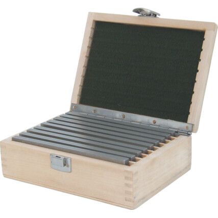
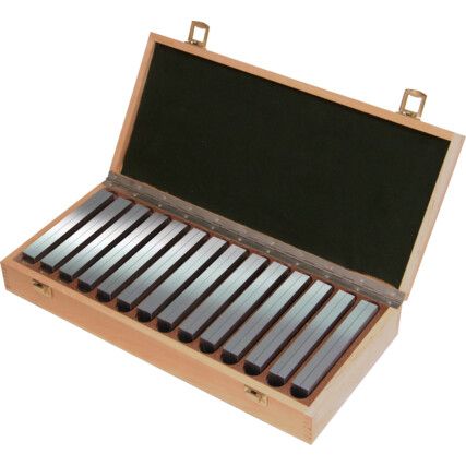
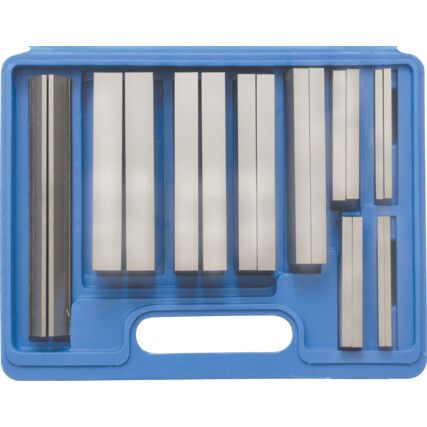
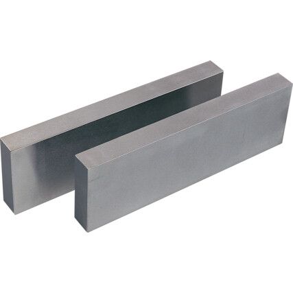
Engineering parallels are a precision-made, matching pairs of rectangular metal blocks that are machined to the exact same dimensions of their matching face to be used within machining operations such as milling, drilling and turning to ensure the workpiece can be accurately held in place. They can be bought as an individual pair, or within a set containing a range of lengths and sizes, generally available in a self-contained wooden protective box ideal for organisation and storage.
Workshop parallels tend to have 4 faces ground, front, back and sides, though some ends also have a smooth surface. Parallels that only have 2 or 4 precision faces tend to have visible tool-marks on non-ground sides from the machining process.
Why engineering parallels?
Engineering parallels are designed to allow accurate placement and alignment of the workpiece within a vice or machining table removing the need for continual manual adjustments with a level, indicator or protractor, or to accurately raise the workpiece to a higher position to give the cutting tool & spindle enough clearance to pass over.
They can be arranged and stacked together to support, both stable & uneven workpieces to create a precise flat profile, crucial in any machining process. Parallels with a good surface tolerance, can become slightly bonded when sliding or rotating two parallels together, as the smooth surfaces creates a temporary molecular attraction known as wringing, which reduces inaccuracies which is also found with gauge blocks. Typically, parallels are manufactured with a series drilled holes on the front face that allows them to be secured with a t-slot clamps.
When are engineering parallels used?
Engineering parallels are used in workshop, tool rooms or machine shops they are a vital component to ensure the workpiece can be levelled and precisely aligned. They are most often used in the drill press to raise workpieces off the machining table to accurately space the workpiece to a specific size prior to machining or are held within clamps on the machine bed, or in a vice to support or raise, the workpiece to a sufficient enough height to allow the cutting tool to pass over without colliding with your equipment.
Types of engineering parallels?
The surface tolerance of parallels is categorised into two main grades:
• Grade A - Close tolerance processes such as precision machining or inspection.
• Grade B - Lower surface tolerances and for lower-precision machining.
Considerations when choosing engineering parallel?
• Accuracy - Each pair of engineering parallels will have a specific accuracy rating this should be considered to ensure machining accuracy
• Hardness - All engineering parallel pairs have a hardness rating that indicates the optimum tolerance range.
• Metric - Engineering Parallels are manufactured to both metric and imperial dimensions.
Engineering parallels jargon buster
Here at Cromwell, we want to make sure you make a confident purchasing decision, so we've outlined some key terms to help you to better understand our range of engineering parallels.
What does HRC mean when it comes to the hardness of an engineering parallel?
HRC refers to the Rockwell scale which is a way of testing the hardness of a material by measuring the depth of penetration of an indenter under a large load. It is always abbreviated as HR followed by a final letter that denotes which specific load on the Rockwell scale the product was tested under.
FAQs
Do I need to be skilled to use engineering parallels?
No specialist qualification is required to use them, just make ensure they are clean and free of debris or chips.
How do I prevent parallels from falling over in the vice when setting up?
Always ensure they are vertically stood against the vice jaw. The easiest way to do this is to use some small springs. Position a couple of springs in between your parallels to keep them pushed up to the vice jaws as you open and closing the vice. This can also be achieved by using a piece of spring steel and bending into a 'Z' shape that will create a spring to ensure the parallels remain apart.
How are engineering parallels made?
To begin with parallels are roughly manufactured to within a small margin of the overall final measurements, they are then paired and placed in a grinding machine where each face is ground to the precise dimensions. Finishes are then applied with the surface finish usually indicating how it was manufactured, if it was ground, they will be grain showing or if lapped will show a mirrored or smooth finish. Other processes may then include drilling or chamfering the edges to sharpened or remove any burrs, but all parallels are usually hardened.
What materials are parallels made from?
They are most commonly made from hardened ground tool steel, stainless steel or cast iron.